
Hytera M110 Magnetic Mobile Antenna Mount
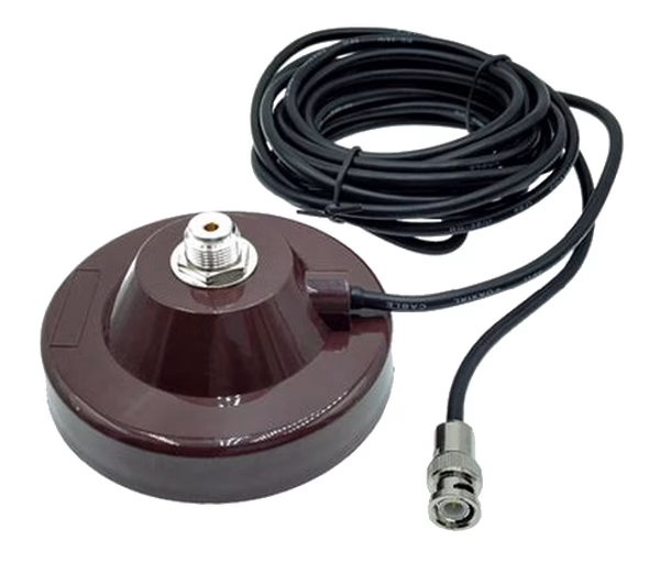
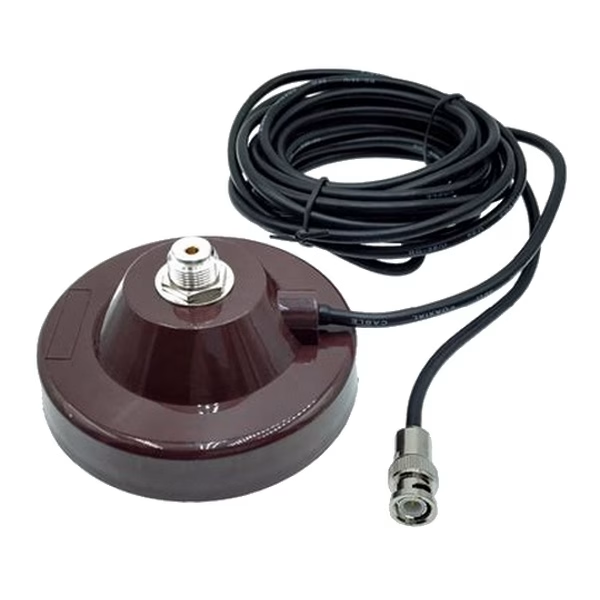
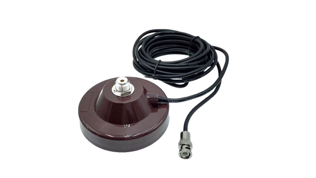
A magnetic mount for a vehicle radio antenna, equipped with a 3 m cable, an SO-239 UHF female mount connector, and a BNC male cable end. It accepts an antenna with a PL-259 connector for a testable mobile installation.
Original price was: 103.50 SAR.98.90 SARCurrent price is: 98.90 SAR. incl. VAT
Available on backorder
RISYS can programme and prepare devices before delivery. Contact us for quantity and project details.
Wholesale and project supply — up to 45% off

Fast shipping





Genuine warranty

Secure payment





B2B/B2C supply
Up to 45% off wholesale supply.
Overview
The Hytera M110 Magnetic Mobile Antenna Mount connects a compatible antenna to a vehicle radio installation through a magnetic mounting point and a cable with defined terminations. The base carries an SO-239 UHF female connector, while the 3 m cable ends in a BNC male connector. This arrangement gives a fleet manager a clear compatibility path: an antenna with a PL-259 connector at the mount and a suitable interface for the BNC male end at the radio or intended assembly. The mount body measures Ø110 × 50 mm and the product weighs 0.76 kg, providing practical references for checking the mounting position and cable route before a vehicle is prepared. Its role is specific to antenna infrastructure; it is not a standalone communications device or the antenna itself, so selection starts with connector matching and the actual distance between the mount and radio.
How the Hytera M110 Magnetic Mobile Antenna Mount Works
The M110 provides the mechanical and cabled link between a compatible vehicle antenna and the route to the radio. The SO-239 female connector fixed at the mount accepts an antenna using a PL-259 connector, and the cable carries the signal to its BNC male termination. Before ordering, a technician can review the antenna end and radio-side interface separately. A successful match at one end does not establish compatibility at the other. This simple separation helps prevent the mount arriving at a site that has the correct antenna but a different radio input, or the opposite combination.
The 3 m cable gives installers a defined boundary for route planning inside the vehicle. Distance should be measured along the proposed route itself, including the path from the mount position to the radio, instead of relying on an estimated straight line. The technician also needs a route that does not pinch the cable or obstruct vehicle components used during normal work. Once the base is positioned and the cable routed, both connectors and cable movement at turns can be inspected before the radio is powered and communications are tested.
Understanding Cable Loss in the Installation
The cable has a stated loss of no more than 0.3 dB/m from 0-500 MHz and no more than 0.7 dB/m from 500-1000 MHz. These values give a communications technician a basis for reviewing the signal route in relation to the frequency range used, while accounting for the complete 3 m cable length. They also support keeping the path purposeful and avoiding unnecessary extensions or additional connections outside the stated configuration. Installation decisions should remain tied to the route and connectors that the team has actually inspected.
During assembly testing, the team can record the operating band of the radio and antenna, the route used, and the condition of the SO-239 and BNC connectors. Transmit and receive checks can then be completed at the vehicle’s operating locations. Cable-loss figures alone do not promise identical coverage at every site; they describe the cable within the stated ranges, while acceptance depends on the antenna, radio, mount position, and full-system test. Retaining the result with the vehicle identity and connection arrangement gives maintenance staff a useful baseline.
Selecting the Mount Position and Cable Route
The mount body is 110 mm in diameter and 50 mm high, and the product weighs 0.76 kg. These dimensions help a vehicle team identify an area that accommodates the complete base and lets the cable leave in a manageable direction. The mounting point should be cleaned and checked for even contact, followed by confirmation that the base will not interfere with opening a vehicle section or accessing other equipment. Once fitted, a controlled cable check can confirm that ordinary movement does not transfer directly into the connector.
The recommended vehicle speed limit is 80 km/h. This limit should be included in driver guidance and the pre-movement check, with mount retention and the cable route inspected again after repositioning or reinstallation. If the vehicle’s operating duty requires different conditions, the fleet manager should evaluate whether the mounting method fits the organisation’s policy before use. That review keeps deployment connected to the recommended operating limit instead of treating the mount as a component that can be positioned and ignored.
Saudi Fleet Use Cases for the M110
The M110 serves security, facilities, and logistics teams equipping vehicles with compatible radios and antennas. For security patrols, a fleet technician can position the mount, route the 3 m cable to the radio unit, and test communications along the approved patrol routes. For field maintenance vehicles, the clearly identified connectors support a straightforward checklist before each installation: PL-259 at the antenna, SO-239 at the base, and BNC male at the cable termination.
In warehouse and yard operations, an equipment manager can assign an M110 to each vehicle and retain the mount position and cable route in the asset record. Across contractor fleets, consistent component naming helps prevent the antenna mount being confused with the radio or antenna itself. The operational value comes from keeping the system components clear: M110 supplies the stated mount, cable, and connectors, while the selected antenna and radio must fit both connection ends and the organisation’s frequency plan.
M110 Compared with the HP56X UL913 Sibling
M110 differs from the HP56X UL913 in its fundamental role within the family. M110 is an accessory for mounting an antenna in a vehicle radio system, while its sibling is a handheld radio carried by an individual for conversations. The products should therefore not be compared as substitutes performing the same task. If the requirement is to equip a worker with portable communications, the decision belongs to the handheld-radio category. If the requirement is to create an antenna mounting and cable connection point for a vehicle, M110 is the relevant item.
This distinction helps procurement teams structure project lines correctly. The M110 can appear under vehicle installation hardware, with SO-239, BNC, cable length, and the required PL-259 antenna connection recorded. The radio and antenna remain separate items that must be matched to the assembly. In this structure, receiving staff know that delivery of an M110 does not complete the radio system; it delivers the defined component connecting the antenna position to the cable route.
Pre-installation and Handover Checks
Inspection begins by confirming the M110 model identity, followed by checking the Ø110 × 50 mm body and 0.76 kg weight against the planned position. The technician can then inspect the SO-239 connector at the base and the BNC male termination on the cable, followed by matching the PL-259 antenna to the mount. The 3 m route should be measured inside the vehicle before each part is secured, and the cable should be guided without placing continuing strain on its connectors or blocking access to vehicle equipment.
After installation, the team can record the base position, cable path, and connection points, then conduct transmit and receive tests on the intended working band. The test record can reference the cable-loss limits for each frequency range and the recommended 80 km/h speed limit, allowing maintenance staff to see what must be reviewed after a change. An initial-use check should cover mount retention, both connectors, and cable condition along the complete route. When the mount moves to another vehicle, measurement, inspection, and testing should be repeated instead of assuming the previous arrangement will fit the new location. These steps make the M110 a controlled part of a vehicle antenna system that a fleet team can track and maintain.
Technical Specifications
- Brand
- Hytera
- Model
- M110
Frequently Asked Questions
Which connector is fitted to the Hytera M110 mount?
The mount uses an SO-239 UHF female connector and accepts an antenna with a PL-259 connector.
Which connector is fitted to the cable end?
The cable ends in a BNC male connector, so the radio or intended assembly must be matched before ordering.
How long is the M110 cable?
The cable is 3 m long, and its complete route should be measured inside the vehicle before the mount is secured.
What are the M110 mount dimensions and weight?
The mount body measures Ø110 × 50 mm, and the product weighs 0.76 kg.
What vehicle speed is recommended with the mount?
The recommended limit is 80 km/h, with mount retention and the cable route checked before movement and after reinstallation.

Hytera
Hytera makes professional voice, video and data communication devices, systems and software for public safety, energy, transport, utilities and commerce.
Browse brand productsShipping, Warranty and Regulatory
Delivery inside Riyadh
Clear warranty
Some devices or frequencies may require a permit or approval depending on the intended use and the regulations in force in the Kingdom. Requirements are clarified before project orders are fulfilled.
Customer Reviews
No ratings yet for this product
Only logged in customers who have purchased this product may leave a review.
Related Products
Icom BP-264 1420 mAh Ni-MH Battery Pack
On backorder
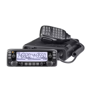
Icom 2730E Dual-Band FM Mobile Transceiver 1052-Channel
On backorder
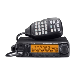
Icom 2300H VHF FM Mobile Transceiver 65 W
In stock — Delivery within 1–3 days
Reviews
There are no reviews yet.